Vibration in metal cutting is familiar to every machine tool operator. This phenomena is recognised in operations such as internal turning, threading, grooving, milling, boring and drilling, to which there are several reasons why this problem occurs. Some are related to the machine tool itself, to the clamping of the tool, the length and diameter of the tool holder and the cutting data to be used.
There are several different actions to consider when solving this problem. Reducing the process parameters is one such consideration, however, this could have a negative effect on productivity. Easy hands on strategy will be emphasized in this guide which will also contain useful information relating to the tool holder e.g. clamping methods, extensions and the types of inserts that can be used.
Stretching beyond the normal limit of 4 x the L/D (Length by Diameter) ratio is possible when using a Silent Tools tool holder. Silent Tools is a Trade Mark for a family of tool holders for turning, milling, boring and drilling with a damper inside to minimise the problems with vibration.
Choosing the right insert can be enough to eliminate vibration and also improve your manufacturing productivity.
Nose radius
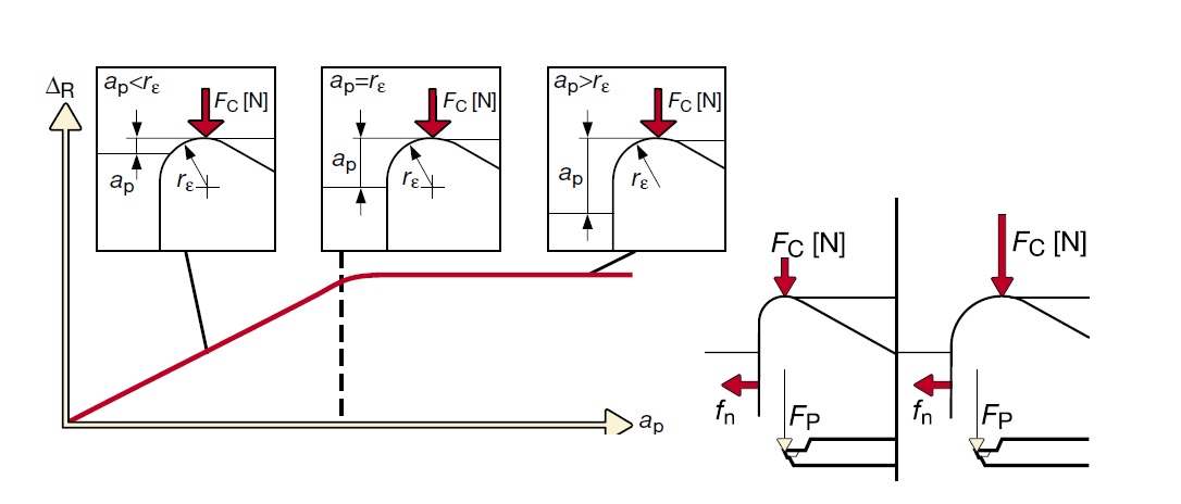
It is important to choose a nose radius that is smaller than the cutting depth as this has the same effect as choosing the correct entering angle. If the nose radius is too large it will push the tool in the radial direction and affect the dimensions of the component. Wiper inserts act as a large nose radius and will generally need a bit more care when applying to internal turning. To decrease the radial cutting forces it is a normal requirement to increase the feed.

Practical hints
Always choose a smaller nose radius than the cutting depth.
Insert size
It is important to choose an insert strong enough to withstand the cutting forces but at the same time it must suit the component and its application. Too large a cutting depth will lead to excessive cutting forces and too small cutting depth will lead to increased friction between the insert and component causing component dimension problems. Cutting force is extremely important when using long overhangs.
Practical hints
Do not exceed 2/3 of the cutting edge length when turning as this will result in too high cutting forces on the cutting edge.
Carbide grade
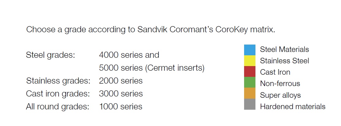
Generally when turning small holes with small boring bars it is bene-ficial to use sharp inserts as this helps to cut the metal more smoothly. Sharp inserts need suitable grades, and grades such as the GC1025 and GC4015, have relatively thin coatings that will enhance the cutting action.

Geometries
Sandvik Coromant geometries are designed and dedicated for each appli-cation area and component materials. Choose your geometry with the application in mind, finishing-roughing, to give the best possible chip breaking together with good machining results. Examples of geometry: PF: Finshing of steel materials; PM: Medium machining of steel materials; and PR: Roughing of steel materials.
Practical hints
Choose an open chip breaker, medium chip breaker (PM), instead of a finishing geometry as the finishing geometry can break the chips too hard and lead to excessive cutting forces resulting in bad surface finish.
1) Insert style
Depending on the operation – longitudinal turning or copying – the choice of insert style affects the result of the machining process.
2) Practical hints
T-style inserts are first choice for internal longitudinal turning as this style of insert uses an entering angle at 91 degrees. This helps to direct the cutting forces correctly.
D and V-style inserts both have good copying possibilities and small insert point angles, which help to reduce the force variation.
3) Tool overhangs:
Depending on the depth of the hole that needs to be turned, it is important to choose the correct type of tool holder and tool holder material.
4) Boring bar materials:
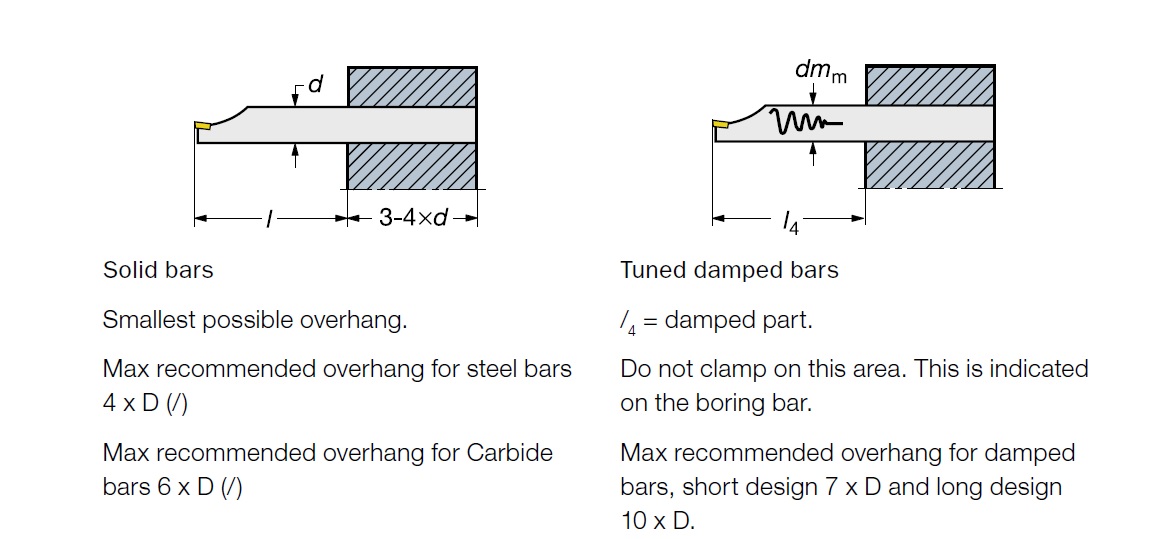
As seen on the diagram the following boring bar materials can be selected to suit the length to diameter ratio overhangs.
Steel boring bars: Up to 4 x D
Carbide boring bars: Up to 6 x D
Steel damped boring bars short design: Up to 7 x D Silent Tools
Steel damped boring bars long design: Up to 10 x D Silent Tools
Carbide reinforced damped boring bars: Up to 14 x D Silent Tools
All damped boring bars are called Silent Tools and consist of different variations of tools, the most common being CoroTurn SL (570) system.


