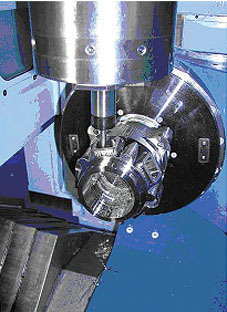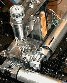
The technological needs when designing machine tools, cutting tools and fixtures using compact moulds and micro-components are increasing. These hold true when enhancing tool paths for any equipment that a machine operator might not be able to identify while it is being cut. One of the processes involved in design is milling. It is defined as the process of cutting materials by feeding a workpiece in a rotating multiple teeth cutter. The cutting movement of the multiple teeth surrounding the milling cutter gives a quick machining method. Machined surfaces may be flat, angular or curved. The surface can also be milled to any desired shapes or a combination of them. Milling machine is known as any tool employed for holding the workpiece, rotating the cutter or feeding it. Without the standard milling operations, the machine operator cannot tell how a tool behaves while it is being cut and the necessary changes will not improve the process. At the same time, the tool path procedures that might be compatible with general milling do not always scale down elegantly for micro-milling applications. As a result, there is a rising demand for small part machining or micro-engineering applications for medical, electronics and optic components. This is where the Swiss-type production machining technology known as micro milling may be very helpful. Generally, the most versatile direct machining process in manufacturing is milling, which is widely used at the micro- scale. Peripheral end milling and slot milling have the most severe machining environment for any micro-mechanical processes. The geometry of a diamond-cutting tool, even in its small width, is a relatively strong structure. When using micro milling, it needs a tool to work as a cantilever beam, which is the weakest structure among the types of cutting tools used for micro chip-making processes. The discovery of the micro-milling process began by simulating the functions of a common four-fluted peripheral end-milling tool. Milling tools are employed with the use of a focused ion beam process (FIB). The FIB is generally used in the semiconductor industry for jobs like mask repair and junction and metallisation layer sectioning. Both tasks exploit the ion beam process in removing unwanted materials at the atomic scale. Members'' contribution A successful company depends on the efficiency of every member of the organisation. Whatever shortcoming brought by any department brings a domino effect in the entire system. In the same way, a machine consists of individual parts. If one component is slightly broken, the machine may not be able to produce the desired result. How the machine is employed and how it behaves in the process will naturally affect the finished product. In micro milling, the proper functioning of the machine''s components is necessary. This means that if there is a slight malfunction in the spindle, it can have a negative impact on the part quality and later lead to total product failure. Micro-milling components are essential to succeed in the production of a quality micro-machined part.

Micro milling is one of the technologies commonly used in producing microstructures and tooling inserts for micro-injection moulding and hot embossing. The on-going trend towards product miniaturisation leads to more micro-technologies, particularly micro milling. Machine segments Machine geometry is critical in achieving the best performance of any machine. This involves identifying the stiffness, accuracy, thermal stability, damping properties, work volume and ease of operator use. Two of the most significant vertical machine geometry types are bridge and C-frame construction, each provides a number of pros and cons. In the C-frame construction, it usually gives the best stiffness for micro-machining as it directly affects ac
Cheap Nike Air Max 2017 For Online Sale The technological needs when designing machine tools, cutting tools and fixtures using compact moulds and micro-components are increasing. These hold true when enhancing tool paths for any equipment that a machine operator might not be able to identify while it is being cut. One of the processes involved in design is milling. It is defined as the process of cutting materials by feeding a workpiece in a rotating multiple teeth cutter. The cutting movement of the multiple teeth surrounding the milling cutter gives a quick machining method. Machined surfaces may be flat, angular or curved. The surface can also be milled to any desired shapes or a combination of them. Milling machine is known as any tool employed for holding the workpiece, rotating the cutter or feeding it. Without the standard milling operations, the machine operator cannot tell how a tool behaves while it is being cut and the necessary changes will not improve the process. At the same time, the tool path procedures that might be compatible with general milling do not always scale down elegantly for micro-milling applications. As a result, there is a rising demand for small part machining or micro-engineering applications for medical, electronics and optic components. This is where the Swiss-type production machining technology known as micro milling may be very helpful. Generally, the most versatile direct machining process in manufacturing is milling, which is widely used at the micro- scale. Peripheral end milling and slot milling have the most severe machining environment for any micro-mechanical processes. The geometry of a diamond-cutting tool, even in its small width, is a relatively strong structure. When using micro milling, it needs a tool to work as a cantilever beam, which is the weakest structure among the types of cutting tools used for micro chip-making processes. The discovery of the micro-milling process began by simulating the functions of a common four-fluted peripheral end-milling tool. Milling tools are employed with the use of a focused ion beam process (FIB). The FIB is generally used in the semiconductor industry for jobs like mask repair and junction and metallisation layer sectioning. Both tasks exploit the ion beam process in removing unwanted materials at the atomic scale. Members'' contribution A successful company depends on the efficiency of every member of the organisation. Whatever shortcoming brought by any department brings a domino effect in the entire system. In the same way, a machine consists of individual parts. If one component is slightly broken, the machine may not be able to produce the desired result. How the machine is employed and how it behaves in the process will naturally affect the finished product. In micro milling, the proper functioning of the machine''s components is necessary. This means that if there is a slight malfunction in the spindle, it can have a negative impact on the part quality and later lead to total product failure. Micro-milling components are essential to succeed in the production of a quality micro-machined part.
  Micro milling is one of the technologies commonly used in producing microstructures and tooling inserts for micro-injection moulding and hot embossing. The on-going trend towards product miniaturisation leads to more micro-technologies, particularly micro milling. Machine segments Machine geometry is critical in achieving the best performance of any machine. This involves identifying the stiffness, accuracy, thermal stability, damping properties, work volume and ease of operator use. Two of the most significant vertical machine geometry types are bridge and C-frame construction, each provides a number of pros and cons. In the C-frame construction, it usually gives the best stiffness for micro-machining as it directly affects acCheap Nike Air Max 2017 For Online Sale


