Design for manufacturability
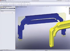
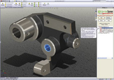
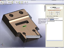
Manufacturing methods predominantly fall within three categories: forming, fabricating, and machining. Each process has its own characteristic production issues, and a range of 3D CAD technologies have emerged to assess DFM for each method. Forming processes use tool - a mold, a pattern or a die - to create the part and include injection-molding, casting, forging, and stamping. Although each of these methods uses different materials and techniques, a common requirement is the need to provide sufficient draft: the minimum taper or angle given to a mold, pattern, or die to ensure the part will pull away easily and blemish-free. Instead of leaving decisions about draft and parting lines to the toolmaker, designers can now use CAD draft and parting line analysis capabilities to ensure proper extraction of the part, while still meeting the functional and aesthetic requirements of the design. Tools are also available for identifying costly undercut features that require sliders or side action, as well as for maintaining uniform wall thicknesses to prevent sink spots. For fabrication, designers can use 3D CAD capabilities to create sheet-metal parts in both flat and bent states; first designing the bent state then automatically creating flat patterns based on bend table and K-factor information for different material types. Designers can export flat patterns directly into laser and water-jet cutting machines for cutting the flat patterns. This eliminates the time-consuming, expensive and often error-prone step of manually converting the bent sheet-metal design into a flat pattern for manufacturing. When machining parts ?whether milling, turning or drilling ?designers can use new 3D CAD capabilities to assess the manufacturability of specific features. These tools help designers check for features that would be impossible or very expensive to machine, such as rounding the outside edge of a machined part to break the edge when a chamfer would be less expensive, or creating a bolt clearance hole that does not match an available machine shop drill size.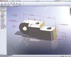
Tolerances and dimensions
3DMens Running Shoes


