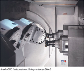
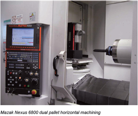
卧式加工中心通常带有分度工作台或数控转换工作台,可加工工件的各个侧面;也可做多个坐标的联合运动,以加工复杂的空间曲面。但它同

Most experienced programmers will agree that horizontal machining centers are among the most difficult metal-cutting CNC machines to program. The primary reason why horizontals are tough to program is that almost all of them incorporate some kind of rotary device in the table (indexer or rotary axis), meaning this kind of machine can expose countless workpiece surfaces to the spindle for machining. With several workpiece surfaces to machine, the related CNC program can become quite lengthy. Program length is not the only factor that contributes to the difficulties related to having the ability to machine multiple workpiece surfaces. With a complex process having many machining operations, even keeping track of what machining must be done on each surface can be a daunting challenge. If efficiency is a concern, developing the program in a manner that requires the fewest tool changes and/or table rotations, while still providing a workable machining order process, can be quite a challenge. Yet another factor that stems from machining multiple workpiece surfaces is related to program zero (origin) selection, which will be the topic for this article. All coordinates in the program, of course, must reflect the current program zero point selection. Since the workpiece will be rotating (table indexing) during the machining cycle, program zero will also be moving. After an index, the program zero point for the previous surface just machined will no longer be correct for the new surface to be machined. Very few horizontal machining centers have the ability to keep track of the program origin during a rotation, meaning the CNC user is left completely on their own to handle this issue. If working on just one workpiece surface, which is commonly the case with vertical machining centers, the program zero point selection and assignment is much easier ?there is only one surface to deal with. The programmer can easily specify programmed coordinates directly from the workpiece drawing. That is, if the intersection of all three datum surfaces on the drawing is made to be the program zero point for the program, all coordinates in the program can reflect drawing dimensions. This in turn, makes programming much simpler. When it comes to making the setup, the measurements related to the (one) program zero assignment will be easy to make and the (three) related program zero assignment values will be easy to enter into (one) fixture offset. By comparison, almost all horizontal machining center applications require that more than one surface of the workpiece be machined by the program. After rotating the workpiece, another surface is exposed to the spindle for machining. Of course, programmed coordinates must still reflect the program zero point location. How is the program zero point location determined in this case? Traditionally there have been two basic schools-ofthought: 1. Come up with a separate program zero location for each surface. This tends to be the method of choice when a programmer has previous experience with vertical machining centers. It simply extends what they do for a vertical machine. If a workpiece is machined on four sides (four workpiece rotations), four separate program zero points will be assigned. This means four fixture offsets will be required. Each containing three program zero assignment values (X, Y, and Z) ? for a total of twelve values that must be measured and entered in this case. 2. Make the center of rotation the program zero point in X and Z and choose a common workpiece surface in the Y axis. With this method, only one program zero point is required (center of rotation). Meaning only one fixture offset and three program zero assignment values. Regardless of which side of the workpiece is being worked on, programmed coordinates come from the same place.

New Balance
 Most experienced programmers will agree that horizontal machining centers are among the most difficult metal-cutting CNC machines to program. The primary reason why horizontals are tough to program is that almost all of them incorporate some kind of rotary device in the table (indexer or rotary axis), meaning this kind of machine can expose countless workpiece surfaces to the spindle for machining. With several workpiece surfaces to machine, the related CNC program can become quite lengthy. Program length is not the only factor that contributes to the difficulties related to having the ability to machine multiple workpiece surfaces. With a complex process having many machining operations, even keeping track of what machining must be done on each surface can be a daunting challenge. If efficiency is a concern, developing the program in a manner that requires the fewest tool changes and/or table rotations, while still providing a workable machining order process, can be quite a challenge. Yet another factor that stems from machining multiple workpiece surfaces is related to program zero (origin) selection, which will be the topic for this article. All coordinates in the program, of course, must reflect the current program zero point selection. Since the workpiece will be rotating (table indexing) during the machining cycle, program zero will also be moving. After an index, the program zero point for the previous surface just machined will no longer be correct for the new surface to be machined. Very few horizontal machining centers have the ability to keep track of the program origin during a rotation, meaning the CNC user is left completely on their own to handle this issue. If working on just one workpiece surface, which is commonly the case with vertical machining centers, the program zero point selection and assignment is much easier ?there is only one surface to deal with. The programmer can easily specify programmed coordinates directly from the workpiece drawing. That is, if the intersection of all three datum surfaces on the drawing is made to be the program zero point for the program, all coordinates in the program can reflect drawing dimensions. This in turn, makes programming much simpler. When it comes to making the setup, the measurements related to the (one) program zero assignment will be easy to make and the (three) related program zero assignment values will be easy to enter into (one) fixture offset. By comparison, almost all horizontal machining center applications require that more than one surface of the workpiece be machined by the program. After rotating the workpiece, another surface is exposed to the spindle for machining. Of course, programmed coordinates must still reflect the program zero point location. How is the program zero point location determined in this case? Traditionally there have been two basic schools-ofthought: 1. Come up with a separate program zero location for each surface. This tends to be the method of choice when a programmer has previous experience with vertical machining centers. It simply extends what they do for a vertical machine. If a workpiece is machined on four sides (four workpiece rotations), four separate program zero points will be assigned. This means four fixture offsets will be required. Each containing three program zero assignment values (X, Y, and Z) ? for a total of twelve values that must be measured and entered in this case. 2. Make the center of rotation the program zero point in X and Z and choose a common workpiece surface in the Y axis. With this method, only one program zero point is required (center of rotation). Meaning only one fixture offset and three program zero assignment values. Regardless of which side of the workpiece is being worked on, programmed coordinates come from the same place.


